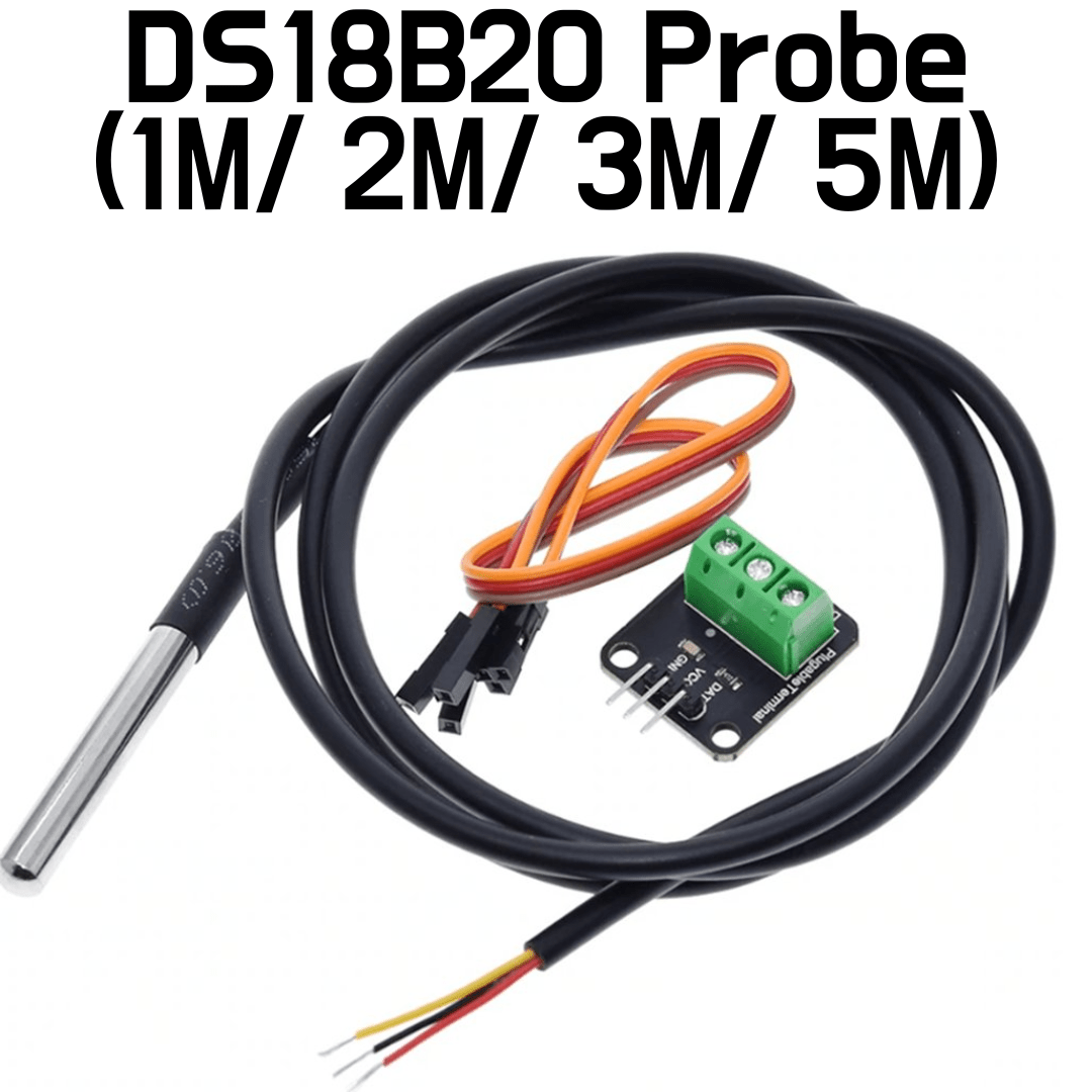
DS18b20 Waterproof temperature probe (1M/ 2M/ 3M/ 5M)

DS18b20 Waterproof temperature probe (1M/ 2M/ 3M/ 5M)
Type
Regular price $6.99
/
  • Free shipping on all orders over $100
  • Secure payments
  • In stock, ready to ship
  • Inventory on the way

Add $100.00 more for free shipping

Tax included. Shipping calculated at checkout.

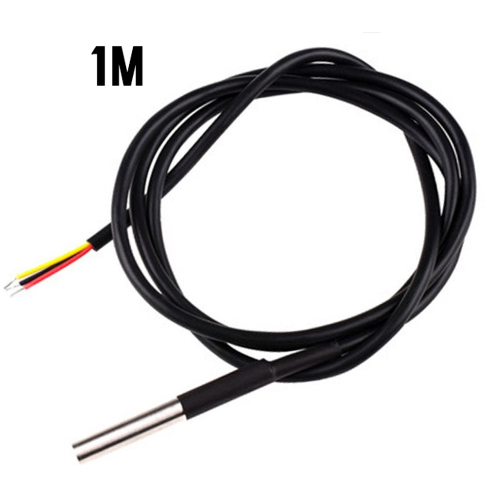
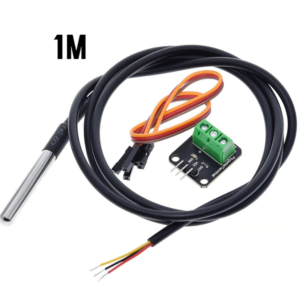
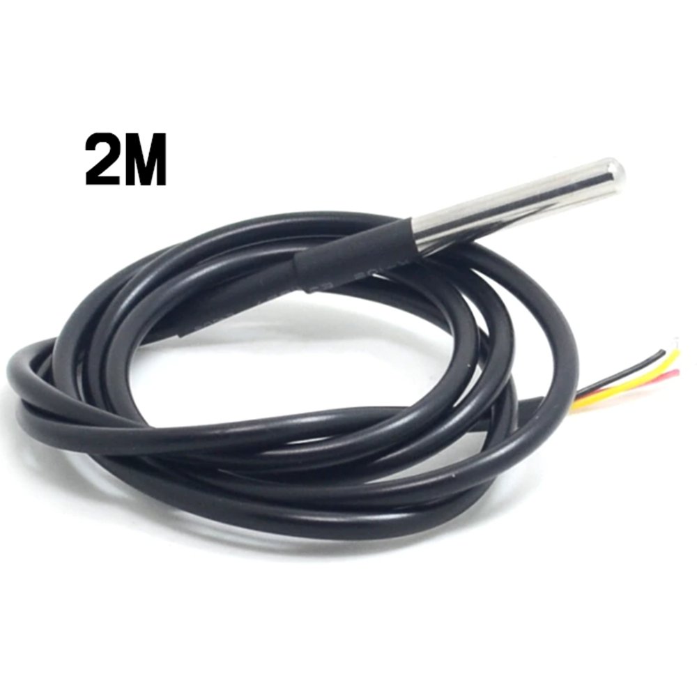
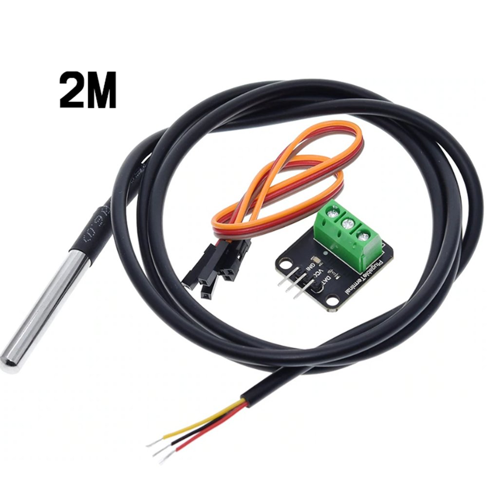
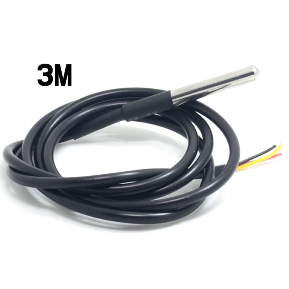
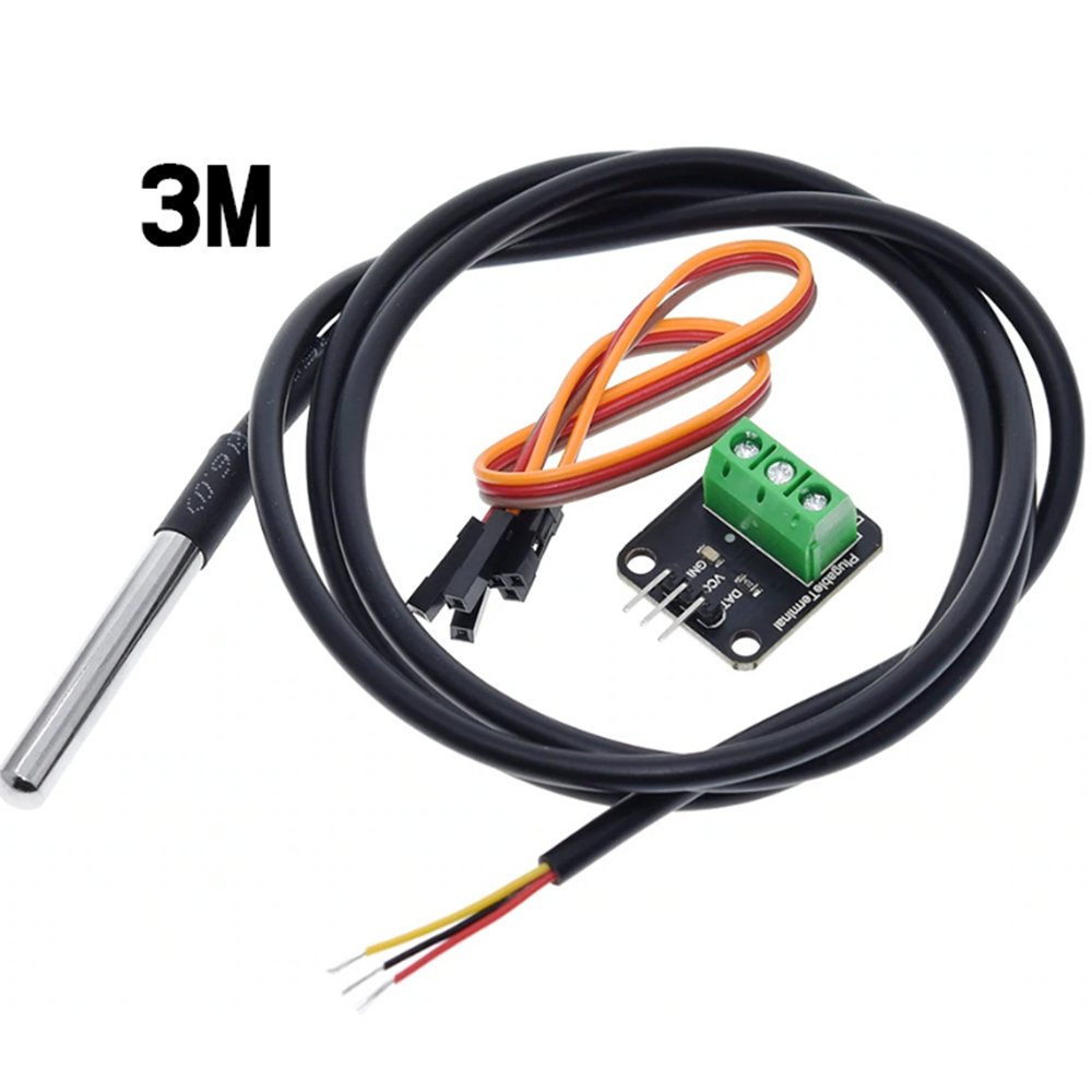
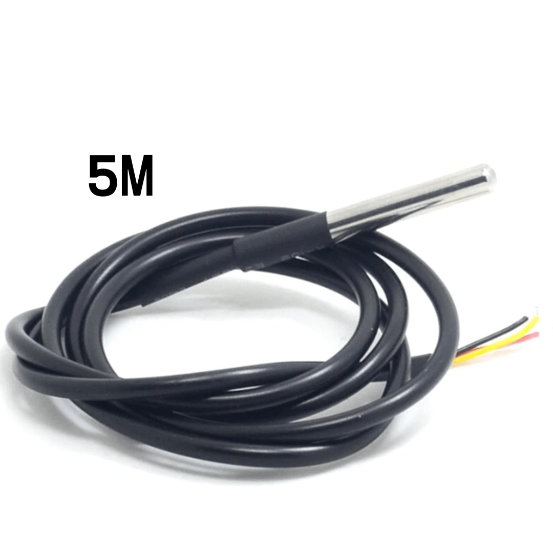
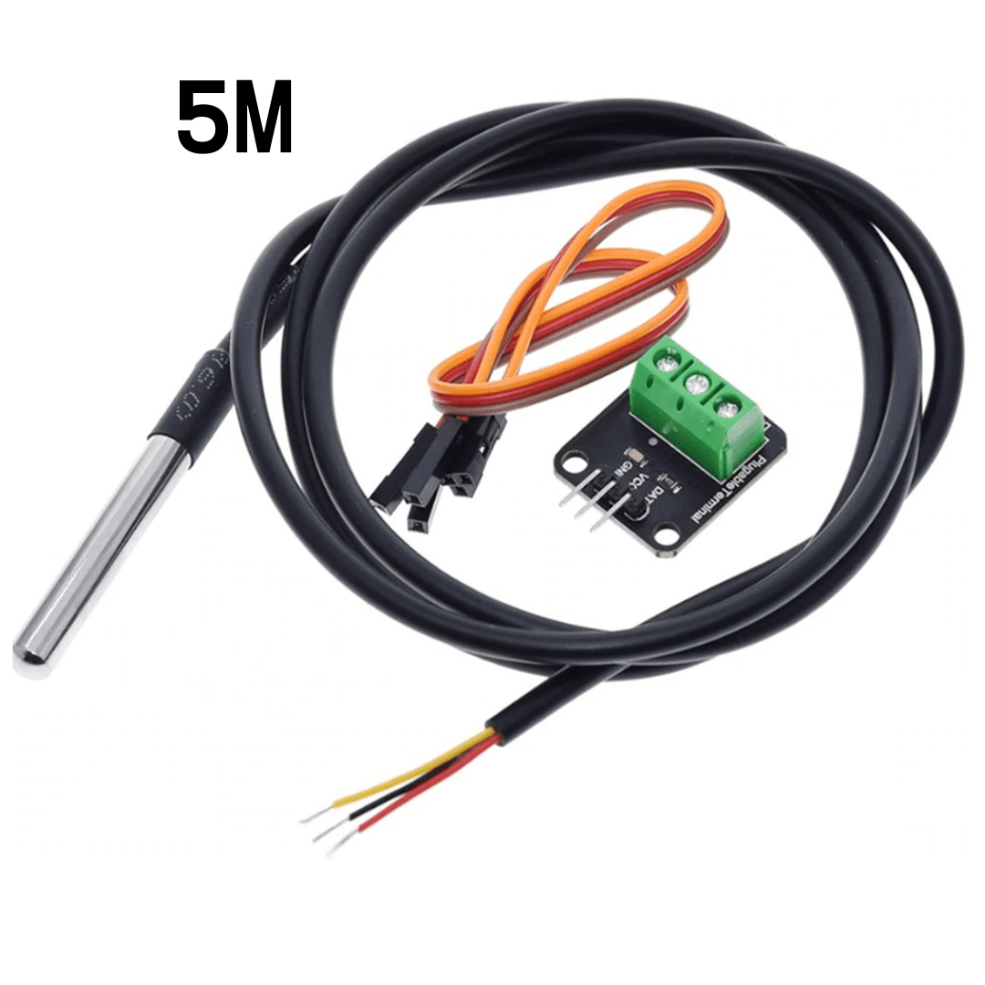
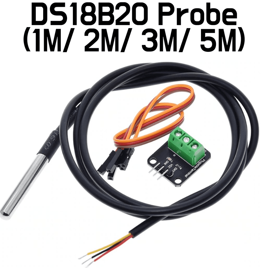
A DS18B20 digital temperature sensor sealed in a stainless steel probe, on a 1 m, 2 m, 3 m or 5 m cable, with an optional adapter board for quick wiring.

The DS18B20 waterproof temperature probe is a 1-Wire digital thermometer that measures −55 °C to +125 °C, with ±0.5 °C accuracy from −10 °C to +85 °C, and runs from a 3.0 V to 5.5 V supply. It needs only one data pin on an Arduino, ESP32 or Raspberry Pi, and several probes can share that same pin, so it suits aquariums, brewing, soil and greenhouse logging, and freezer or hot-water monitoring.

Range
−55 °C to +125 °C
Accuracy
±0.5 °C (−10 to +85 °C)
Interface
1-Wire digital
Supply
3.0 V to 5.5 V

Why choose it

  • Digital reading, no calibration maths — the DS18B20 converts temperature on the chip and sends it as a 9- to 12-bit value (0.0625 °C steps at 12-bit), so long cables do not shift the reading the way they can with analogue sensors.
  • Many probes on one pin — every DS18B20 has its own factory-programmed 64-bit serial code, so you can connect several probes in parallel to a single data pin and read each one separately.
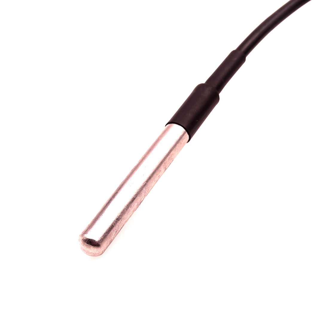
  • Ready for wet places — the sensor sits inside a sealed 6 × 50 mm stainless steel tube on a sheathed cable, so it can go into water, soil or a fermenter while the electronics stay dry.

Specifications

Sensor
Sensor IC DS18B20 1-Wire digital thermometer
Measuring range −55 °C to +125 °C
Accuracy ±0.5 °C (−10 °C to +85 °C); ±1 °C (−30 °C to +100 °C); ±2 °C (−55 °C to +125 °C)
Resolution 9 to 12 bit, user-selectable (0.5 / 0.25 / 0.125 / 0.0625 °C); 12-bit at power-up
Conversion time (max) 750 ms at 12-bit; 93.75 ms at 9-bit
Interface 1-Wire (one data line), unique 64-bit serial code per sensor
Power
Supply voltage 3.0 V to 5.5 V
Active current 1.5 mA max during conversion
Data line pull-up 4.7 kΩ from DATA to VCC (needed with the probe-only option; fitted on the adapter board)
Physical
Probe housing Stainless steel tube, 6 × 50 mm
Cable length 1 m, 2 m, 3 m or 5 m (choose when ordering)
Wire colours Red = VCC, Yellow = DATA, Black = GND
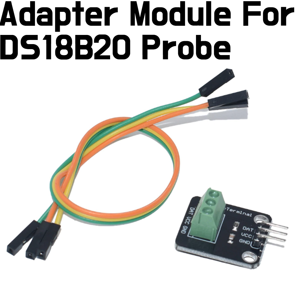
Adapter board (“+ Adapter” options) 3-way screw terminal (DAT, VCC, GND) and 3-pin header (DAT, VCC, GND)

Compatibility

Platform Works Notes
Arduino UNO / Nano (5 V) ✓ Yes Power from 5V; 4.7 kΩ pull-up from DATA to 5V (or use the adapter board)
ESP32 / ESP8266 (3.3 V) ✓ Yes Power from 3V3 and pull DATA up to 3V3, not 5 V
Raspberry Pi ✓ Yes Power from 3.3 V and enable the 1-Wire interface (w1-gpio)
Arduino IDE ✓ Yes “DallasTemperature” library by Miles Burton + “OneWire” library by Paul Stoffregen

In the box

Included
  • 1 × DS18B20 waterproof temperature probe with the cable length you choose (1 m, 2 m, 3 m or 5 m)
  • “+ Adapter” options also include: 1 × DS18B20 adapter board (screw terminal + 3-pin header) and 1 × 3-wire female jumper lead

Applications

  • Aquarium and fish-tank water temperature monitoring
  • Home brewing and fermentation temperature logging
  • Soil, greenhouse and weather-station temperature measurement
  • Fridge, freezer and hot-water cylinder monitoring with several probes on one pin

Quick start

Part 1 — Wire the probe to an Arduino UNO

This guide uses an Arduino UNO because the DS18B20 runs happily at 5 V and the UNO is the easiest board to start with.

1
Probe-only option: add the 4.7 kΩ pull-up
Connect red to 5V, black to GND and yellow to D2. Then place a 4.7 kΩ resistor between the yellow (DATA) wire and 5V, as shown below. Without this resistor the sensor will not be found.
2
“+ Adapter” option: use the screw terminal instead
Screw the probe wires into the terminal: yellow to DAT, red to VCC, black to GND. Then use the jumper lead to connect the header pins to the UNO: DAT to D2, VCC to 5V, GND to GND. The pull-up resistor is already on the adapter board, so you do not need a separate one.
Arduino UNO 5VD2GND DS18B20 probe Red (VCC)Yellow (DATA)Black (GND) 4.7 kΩ pull-up
Probe wire Arduino UNO pin Notes
Red (VCC) 5V Power, 3.0 V to 5.5 V
Yellow (DATA) D2 1-Wire data; 4.7 kΩ pull-up to 5V
Black (GND) GND Ground

Part 2 — Install the libraries and read your first temperature

3
Install the two libraries
In the Arduino IDE open Tools → Manage Libraries…. Search for DallasTemperature and install the library by Miles Burton. Then search for OneWire and install the library by Paul Stoffregen (if the IDE offers to install it as a dependency, click Install All).
4
Select the board and port
Plug in the UNO with its USB cable. Choose Tools → Board → Arduino AVR Boards → Arduino Uno, then pick the UNO's port under Tools → Port.
5
Upload Example 1 and open the Serial Monitor
Paste the sketch below, click Upload, then open Tools → Serial Monitor and set it to 9600 baud. You should see “Probes found: 1” and then a new temperature in °C every second. Hold the probe tip in your hand and watch the value rise.
▸ Example 1 — Read one probe
#include <OneWire.h>
#include <DallasTemperature.h>

#define ONE_WIRE_BUS 2   // yellow DATA wire on D2

OneWire oneWire(ONE_WIRE_BUS);          // 1-Wire bus on D2
DallasTemperature sensors(&oneWire);   // DS18B20 driver on that bus

void setup() {
  Serial.begin(9600);
  sensors.begin();                      // search the bus for probes
  Serial.print("Probes found: ");
  Serial.println(sensors.getDeviceCount());
}

void loop() {
  sensors.requestTemperatures();             // start a conversion on every probe
  float tempC = sensors.getTempCByIndex(0);  // read the first probe

  if (tempC == DEVICE_DISCONNECTED_C) {      // -127 means no reply
    Serial.println("Error: probe not found - check wiring and pull-up");
  } else {
    Serial.print("Temperature: ");
    Serial.print(tempC);
    Serial.println(" C");
  }
  delay(1000);
}

Part 3 — Several probes on one pin with a temperature alarm

6
Add more probes in parallel
Connect every probe's red wire to 5V, every black wire to GND and every yellow wire to D2. Keep just one 4.7 kΩ pull-up between D2 and 5V for the whole bus (or one adapter board). Each probe is identified by its own 64-bit address, so no extra pins are needed.
7
Upload Example 2
The sketch lists each probe's address once, then prints every probe's temperature every 2 seconds. If any probe reads above ALARM_C (30 °C here), the UNO's built-in LED (marked “L”) turns on. Warm one probe in your hand or in a cup of warm water to test it. Write down which address belongs to which probe so you can label them.
▸ Example 2 — Multiple probes + over-temperature LED
#include <OneWire.h>
#include <DallasTemperature.h>

#define ONE_WIRE_BUS 2          // all yellow DATA wires on D2
const float ALARM_C = 30.0;     // LED turns on above this temperature

OneWire oneWire(ONE_WIRE_BUS);
DallasTemperature sensors(&oneWire);
DeviceAddress addr;             // 8-byte address buffer
uint8_t count = 0;

void printAddress(DeviceAddress a) {
  for (uint8_t i = 0; i < 8; i++) {
    if (a[i] < 16) Serial.print("0");
    Serial.print(a[i], HEX);
  }
}

void setup() {
  Serial.begin(9600);
  pinMode(LED_BUILTIN, OUTPUT);
  sensors.begin();
  count = sensors.getDeviceCount();
  Serial.print("Probes found: ");
  Serial.println(count);

  for (uint8_t i = 0; i < count; i++) {
    if (sensors.getAddress(addr, i)) {
      sensors.setResolution(addr, 12);  // 0.0625 C steps
      Serial.print("Probe ");
      Serial.print(i);
      Serial.print(" address: ");
      printAddress(addr);
      Serial.println();
    }
  }
}

void loop() {
  sensors.requestTemperatures();   // all probes convert at the same time
  bool alarm = false;

  for (uint8_t i = 0; i < count; i++) {
    if (!sensors.getAddress(addr, i)) continue;
    float t = sensors.getTempC(addr);
    Serial.print("Probe ");
    Serial.print(i);
    Serial.print(": ");
    if (t == DEVICE_DISCONNECTED_C) {
      Serial.println("not responding");
      continue;
    }
    Serial.print(t);
    Serial.println(" C");
    if (t > ALARM_C) alarm = true;
  }

  digitalWrite(LED_BUILTIN, alarm ? HIGH : LOW);
  Serial.println("---");
  delay(2000);
}

Troubleshooting

Problem Likely cause Fix
“Probes found: 0” or reading −127 °C No pull-up resistor, DATA on the wrong pin, or a loose wire Check the 4.7 kΩ between DATA and 5V, confirm yellow goes to D2, and re-seat every connection
Reading stays at 85.00 °C 85 °C is the sensor's power-on value, so the conversion did not finish Make sure red goes to 5V (not left unconnected) and the supply is steady
Compile error “DallasTemperature.h: No such file or directory” Library not installed Install both DallasTemperature and OneWire in Library Manager (step 3)
Serial Monitor shows random characters Baud rate mismatch Set the Serial Monitor to 9600 baud
Good to know
  • The probe-only option needs a 4.7 kΩ pull-up resistor between DATA and VCC. The “+ Adapter” options have it on the board.
  • Check the wire colours before powering up. Swapping VCC and GND can damage the sensor.
  • On 3.3 V boards (ESP32, ESP8266, Raspberry Pi), power the probe and pull DATA up to 3.3 V, not 5 V.
  • ±0.5 °C accuracy applies from −10 °C to +85 °C; outside that the datasheet allows up to ±2 °C.
  • The −55 °C to +125 °C range is the rating of the DS18B20 chip.
  • Only the stainless steel tip and cable are sealed. Keep the bare wire ends and the adapter board dry.

Video guide

Resources

FAQ

▸ Do I need a resistor to use this probe?

Yes for the probe-only option: fit a 4.7 kΩ resistor between the yellow DATA wire and VCC. The “+ Adapter” options already have the pull-up on the adapter board.

▸ Can I connect several probes to one Arduino pin?

Yes. Each DS18B20 has a unique 64-bit serial code, so you can wire several probes in parallel to one data pin with a single pull-up and read each one by its address (see Example 2).

▸ Does it work with an ESP32 or other 3.3 V board?

Yes. The DS18B20 runs from 3.0 V to 5.5 V, so power it from 3.3 V and pull the data line up to 3.3 V. The same Arduino libraries work on ESP32.

▸ How accurate is it?

±0.5 °C from −10 °C to +85 °C, according to the DS18B20 datasheet. It is ±1 °C from −30 °C to +100 °C and ±2 °C across the full −55 °C to +125 °C range.

▸ Why do I get −127 °C or 85 °C?

−127 °C means the library got no reply from the sensor, usually a missing pull-up or loose wire. 85 °C is the sensor's power-on value, which shows up when a conversion did not complete, often because of a power problem.

▸ What is the difference between the probe and “+ Adapter” options?

The probe is the same in both. The “+ Adapter” options add a small board with a screw terminal for the probe wires, a built-in pull-up resistor and a 3-pin header, plus a 3-wire jumper lead, so you can connect to a board without a breadboard or separate resistor.

Technical question about this part? Email support@epartners.co.nz with your board and wiring, and we'll help you get it working.

Shipping: $5.99 urban, $9.99 rural. Free shipping on orders of $100 or more.

Order by 10:30am (NZT), Monday to Friday, and we dispatch the same day. Orders placed after 10:30am, on weekends or on public holidays are dispatched the next business day.

Delivery usually takes 1–2 business days after dispatch (2–3 for rural addresses). See our Shipping Policy for full details.

This site is protected by hCaptcha and the hCaptcha Privacy Policy and Terms of Service apply.

Recently viewed