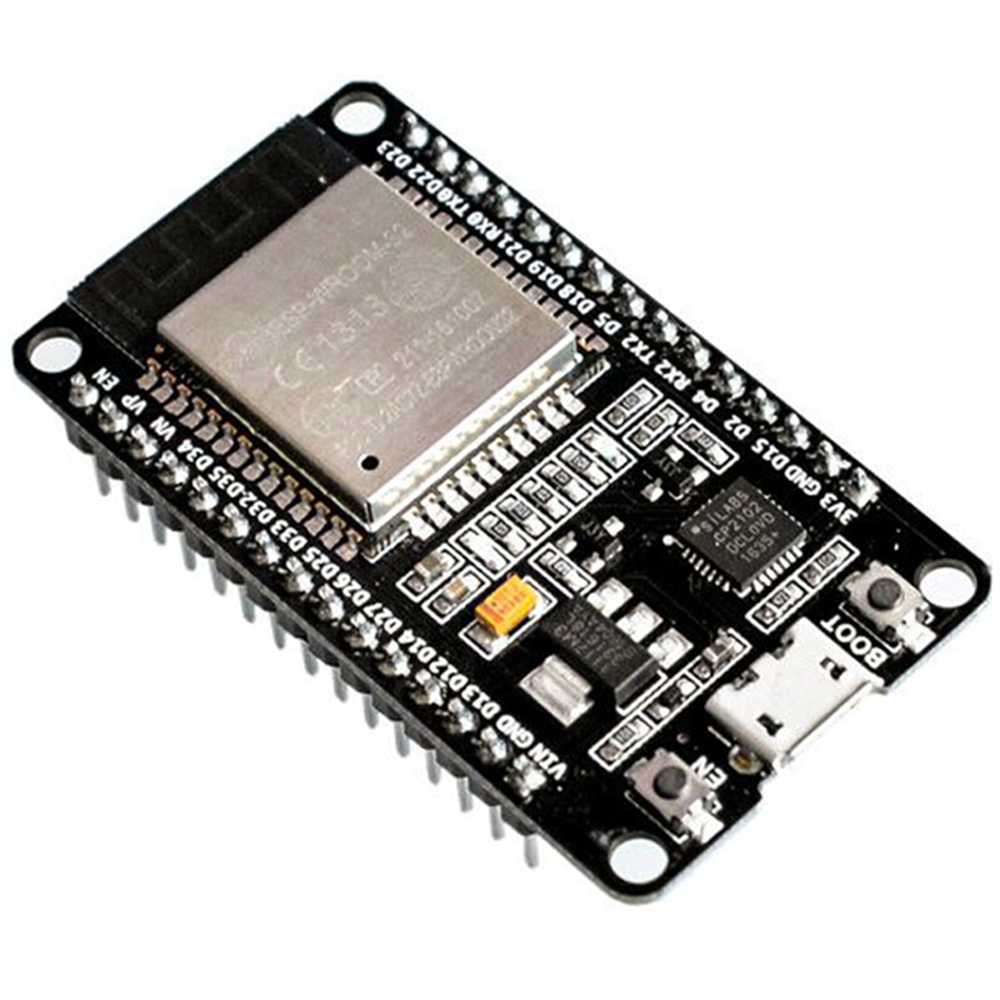
The ESP32-S3 N16R8 is a development board built on the Espressif ESP32-S3-WROOM-1-N16R8 module, with a 240 MHz dual-core LX7 CPU, 16 MB flash, 8 MB Octal PSRAM, 2.4 GHz Wi-Fi, Bluetooth LE 5 and two USB-C ports.
The large flash and PSRAM give room for web dashboards, display and camera projects and large data buffers that do not fit on a standard ESP32. It suits makers, students and engineers moving up from the original ESP32 who want native USB and more memory.
Why choose it
- Memory for bigger projects — 16 MB flash and 8 MB Octal PSRAM, compared with 4 MB flash and no PSRAM on a typical ESP32-WROOM-32 board.
- Two USB-C ports — one goes to a CH343P USB-to-serial chip for easy uploading, the other to the ESP32-S3's native USB for USB OTG and USB Serial/JTAG debugging.
- Interfaces for displays and cameras — the ESP32-S3 has an LCD interface, a camera interface, touch sensing and a TWAI® (CAN) controller alongside SPI, I2C, I2S and UART.
Specifications
| Core | |
|---|---|
| Module | Espressif ESP32-S3-WROOM-1-N16R8 (on-board PCB antenna) |
| CPU | Xtensa® dual-core 32-bit LX7 with single-precision FPU, up to 240 MHz |
| ROM / SRAM | 384 KB ROM · 512 KB SRAM · 16 KB SRAM in RTC |
| Flash | 16 MB (Quad SPI) |
| PSRAM | 8 MB (Octal SPI) |
| Wireless | |
| Wi-Fi | 802.11b/g/n, 2.4 GHz (2412–2484 MHz), 802.11n up to 150 Mbps |
| Bluetooth | Bluetooth LE: Bluetooth 5, Bluetooth mesh (no Bluetooth Classic) |
| I/O and board | |
| GPIO | 36 GPIOs on the module; GPIO35, GPIO36 and GPIO37 are connected to the Octal PSRAM and are not available |
| Peripherals | SPI, LCD interface, camera interface, UART, I2C, I2S, remote control (IR), pulse counter, LED PWM, MCPWM, SD/MMC host, TWAI® (CAN, ISO 11898-1), ADC, touch sensor, temperature sensor, full-speed USB 2.0 OTG, USB Serial/JTAG |
| USB | 2 × USB-C: native ESP32-S3 USB (GPIO19/GPIO20, USB OTG) and USB-to-serial (CH343P) |
| On-board | BOOT and RST buttons, WS2812 RGB LED on GPIO48, power, TX and RX LEDs |
| Power | |
| Board supply | 5 V through either USB-C port |
| Module supply | 3.0–3.6 V (3.3 V regulated on board) |
| GPIO logic level | 3.3 V |
| Physical | |
| Dimensions | 57 × 28 mm |
| Operating ambient temperature | –40 to 65 °C (N16R8 module rating) |
Compatibility
| Platform | Works | Notes |
|---|---|---|
| Arduino IDE | ✓ Yes | Espressif esp32 board package 3.x, board “ESP32S3 Dev Module” |
| MicroPython | ✓ Yes | ESP32_GENERIC_S3 firmware, SPIRAM_OCT variant (for Octal PSRAM) |
| ESP-IDF / ESPHome | ✓ Yes | Target esp32s3; set 16 MB flash and Octal PSRAM in the project configuration |
| 3.3 V sensors and modules | ✓ Yes | Connect directly to GPIO |
| 5 V logic modules (e.g. Arduino UNO shields) | ◐ With adapter | Use a logic level shifter; GPIO is not 5 V tolerant |
| Raspberry Pi (UART / I2C link) | ✓ Yes | Both sides use 3.3 V logic; connect GND to GND |
In the box
- 1 × ESP32-S3 N16R8 Development Board
Applications
- Wi-Fi web dashboards and data loggers that keep large buffers or files in PSRAM and flash
- Projects with SPI or parallel LCD displays and camera modules
- Bluetooth LE sensors and controllers
- USB devices such as keyboards or MIDI controllers using the native USB OTG port
- Home automation nodes with ESPHome and Home Assistant
Quick start
Part 1 — Set up the Arduino IDE (once only)
Download Arduino IDE 2 from arduino.cc/en/software and install it.
Open File > Preferences and paste this into Additional boards manager URLs:
https://espressif.github.io/arduino-esp32/package_esp32_index.jsonThen open Tools > Board > Boards Manager, search esp32 and install esp32 by Espressif Systems (version 3.x).
Tools > Board > esp32 > ESP32S3 Dev Module, then set:
• Flash Size: 16MB (128Mb)
• PSRAM: OPI PSRAM
• Partition Scheme: 16M Flash (3MB APP/9.9MB FATFS)
• USB CDC On Boot: Disabled (when uploading through the CH343P port)
Part 2 — Upload your first sketch
With the antenna end of the board at the top, the right-hand USB-C port is the CH343P USB-to-serial port and the left-hand one is the native USB port. Plug a USB data cable into the CH343P port, then select the new port in Tools > Port (COMx on Windows, /dev/cu.usbmodem… or /dev/cu.wchusbserial… on macOS, /dev/ttyACM0 on Linux).
Paste Example 1, click Upload, then open Tools > Serial Monitor at 115200 baud and press RST. You should see “ESP32-S3”, 2 cores, 240 MHz, a 16 MB flash size and a PSRAM size close to 8 MB, and the RGB LED cycles red, green and blue.
▸ Example 1 — Check flash and PSRAM, blink the RGB LED
// Example 1 - check the chip, flash and PSRAM, then cycle the onboard RGB LED
// Board: ESP32S3 Dev Module | Flash Size: 16MB (128Mb) | PSRAM: OPI PSRAM
// Upload through the CH343P (USB-to-serial) USB-C port, Serial Monitor at 115200 baud
const uint8_t LED_PIN = 48; // onboard WS2812 RGB LED
void setup() {
Serial.begin(115200);
delay(1000); // give the Serial Monitor a moment to open
Serial.printf("Chip: %s, %d cores, %lu MHz\n",
ESP.getChipModel(), ESP.getChipCores(),
(unsigned long)ESP.getCpuFreqMHz());
Serial.printf("Flash size: %lu MB\n",
(unsigned long)(ESP.getFlashChipSize() / (1024 * 1024)));
if (psramFound()) {
Serial.printf("PSRAM size: %lu KB\n", (unsigned long)(ESP.getPsramSize() / 1024));
} else {
Serial.println("PSRAM not found - set Tools > PSRAM to OPI PSRAM");
}
}
void loop() {
rgbLedWrite(LED_PIN, 40, 0, 0); // red (0-255, kept low so it is not too bright)
delay(500);
rgbLedWrite(LED_PIN, 0, 40, 0); // green
delay(500);
rgbLedWrite(LED_PIN, 0, 0, 40); // blue
delay(500);
rgbLedWrite(LED_PIN, 0, 0, 0); // off
delay(500);
}Part 3 — Wi-Fi web page that controls the RGB LED
Copy Example 2, change
WIFI_SSID and WIFI_PASS to your 2.4 GHz network, keep the same Tools settings and upload. The WiFi and WebServer libraries are part of the ESP32 board package, so nothing extra needs installing.Open the Serial Monitor at 115200 baud. When it prints Open this address in your browser: http://192.168.x.x, open that address on a phone or computer on the same network. Tap Red, Green, Blue or Off to change the LED; the page also shows free PSRAM and uptime.
▸ Example 2 — Wi-Fi RGB LED web page
// Example 2 - Wi-Fi web page that sets the RGB LED colour and shows free PSRAM
// Same Tools settings as Example 1. Your Wi-Fi must be 2.4 GHz.
#include <WiFi.h>
#include <WebServer.h>
const char* WIFI_SSID = "YourNetworkName"; // change to your Wi-Fi name
const char* WIFI_PASS = "YourPassword"; // change to your Wi-Fi password
const uint8_t LED_PIN = 48; // onboard WS2812 RGB LED
WebServer server(80);
void setColour(uint8_t r, uint8_t g, uint8_t b) {
rgbLedWrite(LED_PIN, r, g, b);
}
void handleRoot() {
if (server.hasArg("c")) { // e.g. http://<ip>/?c=red
String c = server.arg("c");
if (c == "red") setColour(40, 0, 0);
else if (c == "green") setColour(0, 40, 0);
else if (c == "blue") setColour(0, 0, 40);
else setColour(0, 0, 0);
}
String html = "<!DOCTYPE html><html><head>"
"<meta name='viewport' content='width=device-width, initial-scale=1'>"
"<title>ESP32-S3 N16R8</title></head>"
"<body style='font-family:sans-serif; padding:16px'>"
"<h1>ESP32-S3 N16R8</h1>"
"<p><a href='/?c=red'>Red</a> | <a href='/?c=green'>Green</a> | "
"<a href='/?c=blue'>Blue</a> | <a href='/?c=off'>Off</a></p>"
"<p>Free PSRAM: " + String(ESP.getFreePsram() / 1024) + " KB</p>"
"<p>Uptime: " + String(millis() / 1000) + " s</p>"
"</body></html>";
server.send(200, "text/html", html);
}
void setup() {
Serial.begin(115200);
setColour(0, 0, 0);
WiFi.mode(WIFI_STA);
WiFi.begin(WIFI_SSID, WIFI_PASS);
Serial.print("Connecting to Wi-Fi");
while (WiFi.status() != WL_CONNECTED) {
delay(500);
Serial.print(".");
}
Serial.println();
Serial.print("Open this address in your browser: http://");
Serial.println(WiFi.localIP());
server.on("/", handleRoot);
server.begin();
}
void loop() {
server.handleClient(); // answer browser requests
}Troubleshooting
| Problem | Likely cause | Fix |
|---|---|---|
| No COM / serial port appears | Charge-only USB cable, or CH343 driver missing | Use a USB data cable. On Windows, install the CH343SER driver from WCH (wch-ic.com) if no port appears |
| “Failed to connect to ESP32-S3” during upload | Board did not enter download mode | Hold BOOT, press and release RST, release BOOT, then upload again |
| “PSRAM not found” or the board resets when using PSRAM | Wrong PSRAM setting | Tools > PSRAM: OPI PSRAM (N16R8 uses Octal PSRAM) |
| Sketch reports 4 MB or 8 MB flash | Flash size left at default | Tools > Flash Size: 16MB (128Mb); Partition Scheme: 16M Flash (3MB APP/9.9MB FATFS) |
| Serial Monitor is blank on the native USB port | USB CDC On Boot is disabled | Use the CH343P port, or set Tools > USB CDC On Boot: Enabled when using the native port |
| RGB LED stays off | RGB solder pad not bridged on some board batches, or wrong pin | Check that the pad marked RGB near the LED is bridged and that LED_PIN is 48 |
| Wi-Fi never connects | 5 GHz network or wrong password | The ESP32-S3 supports 2.4 GHz only; check the network name and password (case-sensitive) |
- GPIO pins use 3.3 V logic and are not 5 V tolerant. Use a level shifter for 5 V modules.
- GPIO35, GPIO36 and GPIO37 are used by the Octal PSRAM on N16R8 — do not connect anything to them.
- GPIO0, GPIO3, GPIO45 and GPIO46 are strapping pins that are read at boot, and GPIO19/GPIO20 are the native USB data lines. Choose other pins first for your own circuits.
- The N16R8 module is rated for –40 to 65 °C ambient temperature.
- Wi-Fi is 2.4 GHz only, and Bluetooth is Bluetooth LE only (no Bluetooth Classic audio or SPP).
Video guide
Resources
- ESP32-S3-WROOM-1 module datasheet (PDF)
- ESP32-S3 chip datasheet (PDF)
- Arduino ESP32 board package — installation guide
- ESP-IDF Get Started for ESP32-S3
- MicroPython firmware for ESP32-S3
FAQ
▸ What does N16R8 mean?
It means 16 MB of flash and 8 MB of PSRAM. On this module the flash is Quad SPI and the PSRAM is Octal SPI, which is why the Arduino PSRAM setting must be “OPI PSRAM”.
▸ Which USB-C port should I use?
Use the CH343P USB-to-serial port for uploading and the Serial Monitor; it is the simplest option. Use the native USB port when you need USB OTG (for example a USB keyboard project) or USB Serial/JTAG debugging, and set USB CDC On Boot to Enabled if you want Serial output on that port.
▸ Does it work with the Arduino IDE?
Yes. Install “esp32 by Espressif Systems” in the Boards Manager and select “ESP32S3 Dev Module” with Flash Size 16MB and PSRAM set to OPI PSRAM, as shown in the Quick start.
▸ Can I connect 5 V sensors directly?
No. The GPIO pins are 3.3 V only. A 5 V sensor output must go through a logic level shifter or a voltage divider before it reaches a GPIO pin.
▸ Does it support Bluetooth Classic, such as A2DP audio or serial port profile?
No. The ESP32-S3 supports Bluetooth LE (Bluetooth 5) only. For Bluetooth Classic projects, use an original ESP32 (ESP32-WROOM-32) board.
▸ How is it different from a standard ESP32 board?
The ESP32-S3 uses dual LX7 cores, has native USB OTG and Bluetooth LE 5, and this N16R8 version adds 16 MB flash and 8 MB PSRAM. The original ESP32 supports Bluetooth Classic but has no native USB.
Technical question about this part? Email support@epartners.co.nz with your board and wiring, and we'll help you get it working.
Shipping: $5.99 urban, $9.99 rural. Free shipping on orders of $100 or more.
Order by 10:30am (NZT), Monday to Friday, and we dispatch the same day. Orders placed after 10:30am, on weekends or on public holidays are dispatched the next business day.
Delivery usually takes 1–2 business days after dispatch (2–3 for rural addresses). See our Shipping Policy for full details.