A 0.91-inch 128 × 32 pixel monochrome OLED display module with the SSD1306 driver chip and a 4-pin I2C interface (GND, VCC, SCL, SDA).
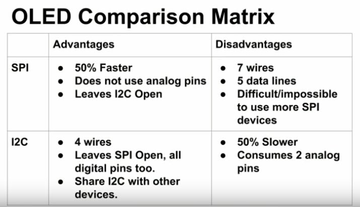
It shows four lines of small text, numbers or simple graphics using only two signal wires, so it suits compact status displays on Arduino, ESP32 and Raspberry Pi Pico projects.
Why choose it
- Only two signal wires — I2C uses SDA and SCL, leaving the rest of your board's pins free.
- No backlight needed — each OLED pixel makes its own light, so text is clear on a black background.
- Widely supported driver — the SSD1306 works with the Adafruit SSD1306 Arduino library, the MicroPython ssd1306 driver and ESPHome.
Specifications
| Display | |
|---|---|
| Screen size | 0.91 in (diagonal) |
| Resolution | 128 × 32 pixels |
| Display type | OLED, monochrome |
| Pixel colour | White (as pictured) |
| Controller & interface | |
| Driver IC | SSD1306 |
| Interface | I2C |
| I2C address | 0x3C (7-bit) |
| Pins | 4 — GND, VCC, SCL, SDA |
| Power | |
| Supply voltage (VCC) | 3.3–5 V |
Compatibility
| Platform | Works | Notes |
|---|---|---|
| Arduino UNO / Nano (5 V) | ✓ Yes | VCC to 5V; SDA → A4, SCL → A5 |
| ESP32 / ESP8266 (3.3 V) | ✓ Yes | Power from 3.3 V; ESP32 default I2C is GPIO21 (SDA) / GPIO22 (SCL) |
| Raspberry Pi Pico / Raspberry Pi | ✓ Yes | Power from 3.3 V; Pico I2C pins are set in code (e.g. GP4/GP5) |
| Software | ✓ Yes | Arduino IDE: Adafruit SSD1306 + Adafruit GFX · MicroPython: ssd1306 driver (micropython-lib) · ESPHome: SSD1306 display component |
In the box
- 1 × 0.91" 128 × 32 OLED display module (I2C, SSD1306)
Applications
- Sensor read-outs — temperature, humidity or distance shown right on the project
- ESP32 status screens — Wi-Fi connection, IP address or the latest value from the internet
- Small clocks and timers with a real-time clock module
- Battery, voltage or counter displays on handheld and wearable builds
Tutorial
What you'll build: show a greeting on the OLED, then a counter that goes up every second — the same result on an Arduino UNO, an ESP32 or a Raspberry Pi Pico. About 20 minutes.
Choose your board
| Board | Logic | Pins used | Language | Best for |
|---|---|---|---|---|
| Arduino UNO | 5 V | A4, A5 | C++ (Arduino IDE) | First-timers |
| ESP32 | 3.3 V | GPIO21, GPIO22 | C++ (Arduino IDE) | Wi-Fi projects |
| Raspberry Pi Pico | 3.3 V | GP4, GP5 | MicroPython (Thonny) | Learning Python |
New to this? Start with the Arduino UNO. Tap a board name below to open its tutorial.
How it works
The board sends a picture to the SSD1306 driver chip on the module over two wires. The chip keeps the picture in its own memory and lights each of the 128 × 32 pixels. Nothing changes on screen until your code says "show" (display.display() or oled.show()), so you draw first, then show.
- GND — the return path for current; the board and module GND must be joined.
- VCC — power for the module (3.3–5 V).
- I2C (SDA + SCL) — two wires: SDA carries the data, SCL is the clock that keeps both sides in step.
- I2C address — the module's "house number" on the two wires, usually 0x3C. The code must use the same number.
- Logic level — the voltage a board treats as "on": 5 V for the UNO, 3.3 V for the ESP32 and Pico.
You need: Arduino UNO R3 + USB cable, 4 × male-to-female jumper wires (module pins → UNO header sockets)
■ Power ■ GND ■ SDA (I2C data) ■ SCL (I2C clock) ⌒ = wires cross, not connected ✕ = do not use
| # | Arduino UNO pin | Module pin | Wire | Notes |
|---|---|---|---|---|
| 1 | 5V | VCC | Red | Power for the module (3.3–5 V supply) |
| 2 | GND | GND | Black | Return path — every GND must be joined |
| 3 | A4 | SDA | Blue | I2C data. On UNO R3 the pin labelled SDA (by AREF) is the same pin as A4 |
| 4 | A5 | SCL | Yellow | I2C clock. The pin labelled SCL is the same pin as A5 |
Watch out: Use A4 and A5 (or the SDA/SCL pins by AREF — they are the same pins). Avoid D0 and D1; they carry the USB serial link.
Connect the four wires as in the table. Match the names printed on the module, not the position — the pin order can differ between production batches.
Download and install the Arduino IDE. Plug the UNO in with a data USB cable, then choose Tools → Board → Arduino Uno and Tools → Port → the port that appeared.
Upload the scanner below, open Tools → Serial Monitor and set it to 115200 baud (the speed the board and computer agree to talk at). You should see
I2C device found at address 0x3C ! then done. If it shows 0x3D, use 0x3D in the example.▸ I2C scanner (Arduino UNO / ESP32)
#include <Wire.h>
void setup()
{
Wire.begin();
Serial.begin(115200);
Serial.println("\nI2C Scanner");
}
void loop()
{
byte error, address;
int nDevices;
Serial.println("Scanning...");
nDevices = 0;
for(address = 1; address < 127; address++ )
{
// The i2c_scanner uses the return value of
// the Write.endTransmisstion to see if
// a device did acknowledge to the address.
Wire.beginTransmission(address);
error = Wire.endTransmission();
if (error == 0)
{
Serial.print("I2C device found at address 0x");
if (address<16)
Serial.print("0");
Serial.print(address,HEX);
Serial.println(" !");
nDevices++;
}
else if (error==4)
{
Serial.print("Unknow error at address 0x");
if (address<16)
Serial.print("0");
Serial.println(address,HEX);
}
}
if (nDevices == 0)
Serial.println("No I2C devices found\n");
else
Serial.println("done\n");
delay(5000); // wait 5 seconds for next scan
}In the Arduino IDE go to Sketch → Include Library → Manage Libraries, search "Adafruit SSD1306" by Adafruit (library page) and click Install. When it asks to install the dependencies, click Install All (this adds the Adafruit GFX Library, which draws the text).
Open a new sketch, paste the code below and click Upload (→). Keep the Serial Monitor at 115200 baud.
▸ Example 1 — Hello + counter (Arduino UNO)
// Wiring (Arduino UNO): VCC->5V, GND->GND, SDA->A4, SCL->A5
#include <Wire.h>
#include <Adafruit_GFX.h>
#include <Adafruit_SSD1306.h>
// UNO I2C pins are fixed: SDA = A4, SCL = A5 (Wire uses them automatically)
const int SCREEN_WIDTH = 128; // OLED width in pixels
const int SCREEN_HEIGHT = 32; // OLED height in pixels - this module is 128x32
const uint8_t OLED_ADDRESS = 0x3C; // ✏️ I2C address - if "not found", try 0x3D
Adafruit_SSD1306 display(SCREEN_WIDTH, SCREEN_HEIGHT, &Wire, -1); // -1 = no reset pin
int count = 0;
void setup() {
Serial.begin(115200); // talk to the computer at 115200 baud
if (!display.begin(SSD1306_SWITCHCAPVCC, OLED_ADDRESS)) {
Serial.println("OLED not found - check wiring");
while (true) { delay(10); } // stop here
}
Serial.println("OK - epartners.co.nz test");
display.clearDisplay();
display.setTextColor(SSD1306_WHITE);
display.setTextSize(1); // small text: 21 characters x 4 lines
display.setCursor(0, 0);
display.println("Hello!");
display.println("epartners.co.nz");
display.display(); // send the picture to the screen
delay(5000); // show epartners.co.nz for about 5 seconds
}
void loop() {
display.clearDisplay();
display.setTextSize(1);
display.setCursor(0, 0);
display.println("Counter");
display.setTextSize(2); // ✏️ bigger text: 10 characters x 2 lines
display.setCursor(0, 14);
display.println(count);
display.display();
Serial.print("Count: ");
Serial.println(count);
count++;
delay(1000); // ✏️ update every 1 second
}✓ Check: The screen shows Hello! and epartners.co.nz for about 5 seconds, then Counter with a number that goes up every second. Serial Monitor (115200 baud) prints OK - epartners.co.nz test once, then Count: 0, Count: 1 …
You need: ESP32 DevKitC, data USB cable, 4 × female-to-female jumper wires
■ Power ■ GND ■ SDA (I2C data) ■ SCL (I2C clock) ⌒ = wires cross, not connected ✕ = do not use
| # | ESP32 pin | Module pin | Wire | Notes |
|---|---|---|---|---|
| 1 | 3V3 | VCC | Red | Use 3V3, not 5V/VIN, so the I2C lines stay at 3.3 V |
| 2 | GND | GND | Black | Any GND pin |
| 3 | GPIO21 | SDA | Blue | Default I2C data pin |
| 4 | GPIO22 | SCL | Yellow | Default I2C clock pin |
Watch out: ESP32 pins are 3.3 V only — never feed a 5 V signal straight in. Power the module from 3V3. Avoid GPIO6–11 (internal flash) and the boot pins GPIO0, 2, 12 and 15.
Connect the four wires as in the table. Match the names printed on the module, not the position.
Install the Arduino IDE. Open File → Preferences and paste this into Additional boards manager URLs:
https://espressif.github.io/arduino-esp32/package_esp32_index.json (Espressif install guide). Then Tools → Board → Boards Manager, search "esp32" and install esp32 by Espressif Systems.Tools → Board → esp32 → ESP32 Dev Module, then Tools → Port. No port? Install the USB driver for the chip on your board: CP210x (Silicon Labs) or CH340 (WCH), and use a data USB cable.
Upload the same I2C scanner as in the Arduino UNO Tutorial (it uses GPIO21/GPIO22 on the ESP32 automatically). Serial Monitor at 115200 baud should show
I2C device found at address 0x3C !.In the Arduino IDE go to Sketch → Include Library → Manage Libraries, search "Adafruit SSD1306" by Adafruit (library page) and click Install. When it asks to install the dependencies, click Install All (this adds the Adafruit GFX Library, which draws the text).
Paste the code below and click Upload. If the upload fails or stops part-way, set Tools → Upload Speed → 115200 and upload again. If it stays on "Connecting…", hold the BOOT button until the upload starts.
▸ Example 1 — Hello + counter (ESP32)
// Wiring (ESP32 DevKitC): VCC->3V3, GND->GND, SDA->GPIO21, SCL->GPIO22
#include <Wire.h>
#include <Adafruit_GFX.h>
#include <Adafruit_SSD1306.h>
const int SDA_PIN = 21; // GPIO21 = SDA (I2C data)
const int SCL_PIN = 22; // GPIO22 = SCL (I2C clock)
const int SCREEN_WIDTH = 128; // OLED width in pixels
const int SCREEN_HEIGHT = 32; // OLED height in pixels - this module is 128x32
const uint8_t OLED_ADDRESS = 0x3C; // ✏️ I2C address - if "not found", try 0x3D
Adafruit_SSD1306 display(SCREEN_WIDTH, SCREEN_HEIGHT, &Wire, -1); // -1 = no reset pin
int count = 0;
void setup() {
Serial.begin(115200); // talk to the computer at 115200 baud
Wire.begin(SDA_PIN, SCL_PIN); // start I2C on the pins above
// last 'false' = Wire is already started, keep our pins
if (!display.begin(SSD1306_SWITCHCAPVCC, OLED_ADDRESS, true, false)) {
Serial.println("OLED not found - check wiring");
while (true) { delay(10); } // stop here
}
Serial.println("OK - epartners.co.nz test");
display.clearDisplay();
display.setTextColor(SSD1306_WHITE);
display.setTextSize(1); // small text: 21 characters x 4 lines
display.setCursor(0, 0);
display.println("Hello!");
display.println("epartners.co.nz");
display.display(); // send the picture to the screen
delay(5000); // show epartners.co.nz for about 5 seconds
}
void loop() {
display.clearDisplay();
display.setTextSize(1);
display.setCursor(0, 0);
display.println("Counter");
display.setTextSize(2); // ✏️ bigger text: 10 characters x 2 lines
display.setCursor(0, 14);
display.println(count);
display.display();
Serial.print("Count: ");
Serial.println(count);
count++;
delay(1000); // ✏️ update every 1 second
}✓ Check: The screen shows Hello! and epartners.co.nz for about 5 seconds, then Counter with a number that goes up every second. Serial Monitor (115200 baud) prints OK - epartners.co.nz test once, then Count: 0, Count: 1 …
You need: Raspberry Pi Pico, data USB cable, 4 × female-to-female jumper wires
■ Power ■ GND ■ SDA (I2C data) ■ SCL (I2C clock) ⌒ = wires cross, not connected ✕ = do not use
| # | Pico pin | Module pin | Wire | Notes |
|---|---|---|---|---|
| 1 | 3V3(OUT) (pin 36) | VCC | Red | Not VBUS (pin 40) — that is 5 V from USB |
| 2 | GND (pin 38) | GND | Black | Any GND pin works (3, 8, 13, 18, 23, 28, 33, 38) |
| 3 | GP4 (pin 6) | SDA | Blue | I2C0 SDA, set in the code |
| 4 | GP5 (pin 7) | SCL | Yellow | I2C0 SCL, set in the code |
Watch out: Pico pins do not tolerate 5 V. Power the module from 3V3(OUT) (pin 36), never from VBUS (pin 40). The I2C pins are set in the code — GP4/GP5 here.
Connect the four wires as in the table. Match the names printed on the module, not the position.
Install Thonny. Hold the BOOTSEL button on the Pico while you plug in the USB cable, then let go. In Thonny choose Run → Configure interpreter → MicroPython (Raspberry Pi Pico) and click Install or update MicroPython (or copy the official UF2 file from micropython.org onto the RPI-RP2 drive).
Paste the three lines below into Thonny and click Run (▶). The Shell should print
[60] — 60 is the decimal form of 0x3C.▸ I2C scan (Pico)
from machine import Pin, I2C
i2c = I2C(0, sda=Pin(4), scl=Pin(5)) # GP4 = SDA, GP5 = SCL
print(i2c.scan()) # expect [60] - 60 is 0x3COpen the official ssd1306.py driver from micropython-lib, copy all of it into a new Thonny file, then File → Save as → Raspberry Pi Pico and name it
ssd1306.py.Open a new file, paste the code below and click Run (▶). Click Stop (■) to end it — the screen clears. To run it on power-up without a computer, save it on the Pico as
main.py.▸ Example 1 — Hello + counter (Pico, MicroPython)
# Wiring (Pico): VCC->3V3(OUT) pin 36, GND->GND pin 38, SDA->GP4 pin 6, SCL->GP5 pin 7
from machine import Pin, I2C
import sys
import time
import ssd1306 # driver from micropython-lib, saved on the Pico as ssd1306.py
SDA_PIN = 4 # GP4 (pin 6) = SDA (I2C data)
SCL_PIN = 5 # GP5 (pin 7) = SCL (I2C clock)
WIDTH = 128 # OLED width in pixels
HEIGHT = 32 # OLED height in pixels - this module is 128x32
OLED_ADDRESS = 0x3C # ✏️ I2C address - if "not found", try 0x3D
i2c = I2C(0, sda=Pin(SDA_PIN), scl=Pin(SCL_PIN), freq=400_000)
if OLED_ADDRESS not in i2c.scan():
print("OLED not found - check wiring")
sys.exit()
oled = ssd1306.SSD1306_I2C(WIDTH, HEIGHT, i2c, addr=OLED_ADDRESS)
print("OK - epartners.co.nz test")
oled.fill(0) # clear the screen
oled.text("Hello!", 0, 0) # 8x8 font: 16 characters x 4 lines
oled.text("epartners.co.nz", 0, 10)
oled.show() # send the picture to the screen
time.sleep(5) # show epartners.co.nz for about 5 seconds
count = 0
try:
while True:
oled.fill(0)
oled.text("Counter", 0, 0)
oled.text(str(count), 0, 16)
oled.show()
print("Count:", count)
count += 1
time.sleep(1) # ✏️ update every 1 second
except KeyboardInterrupt:
oled.fill(0) # clear the screen when you press Stop
oled.show()✓ Check: The screen shows Hello! and epartners.co.nz for about 5 seconds, then Counter with a number that goes up every second. Thonny's Shell prints OK - epartners.co.nz test once, then Count: 0, Count: 1 …
Troubleshooting
| Board | Problem | Likely cause | Fix |
|---|---|---|---|
| All | "OLED not found - check wiring" | SDA and SCL swapped, or a loose wire | Swap SDA/SCL, push each jumper fully on, unplug USB while you change wires |
| All | Scanner finds 0x3D, not 0x3C | This module uses the other address | Set the address to 0x3D in the code |
| All | Text looks squashed or every other line is missing | Code set for a 128 × 64 screen | Set the height to 32 (SCREEN_HEIGHT / HEIGHT) |
| All | Works on the desk, fails with long wires | I2C wires too long | Keep the wires under 20 cm |
| Arduino UNO | No port in Tools → Port | Charge-only USB cable | Use a data USB cable |
| ESP32 | Stuck on "Connecting…" | Board not in upload mode | Hold BOOT until the upload starts |
| ESP32 | Upload fails or stops part-way | Upload speed too high for the USB cable or USB chip | Tools → Upload Speed → 115200, then upload again |
| ESP32 | No port appears | USB driver missing | Install the CP210x or CH340 driver |
| Pico | No RPI-RP2 drive appears | BOOTSEL not held | Unplug, hold BOOTSEL, plug in, then let go |
| Pico | ImportError: no module named 'ssd1306' | Driver not saved on the Pico | Save ssd1306.py on the Pico (step 4) |
Try next: show a sensor reading (e.g. temperature) instead of the counter, or make your name scroll sideways — hint: move the text's x position a little on every loop.
Spotted a problem in this tutorial? Email support@epartners.co.nz and we'll check it and update the tutorial.
- Unplug the USB cable before you connect or move any wire.
- Never swap VCC and GND — follow the names printed on the module, as the pin order can differ between batches.
- On 3.3 V boards (ESP32, Raspberry Pi Pico) power the module from 3.3 V, not 5 V.
Video guide
Resources
- SSD1306 controller datasheet (Solomon Systech, PDF)
- Adafruit SSD1306 Arduino library and Adafruit GFX Library
- MicroPython ssd1306 driver (micropython-lib) · MicroPython quick reference for the Pico (I2C)
- Arduino IDE · Thonny · MicroPython firmware for Raspberry Pi Pico
- Installing Arduino-ESP32 (Espressif) · CP210x USB driver · CH340 USB driver
- Raspberry Pi Pico datasheet (pinout) · Arduino UNO R3 documentation
FAQ
▸ Does it work with a 5 V Arduino UNO?
Yes. The module takes a 3.3–5 V supply; connect VCC to 5V, SDA to A4 and SCL to A5.
▸ What is the I2C address?
Usually 0x3C. Run the I2C scanner in the Tutorial to confirm — if it reports 0x3D, use that in your code.
▸ Which library should I use?
On Arduino and ESP32, install "Adafruit SSD1306" by Adafruit (it also installs Adafruit GFX). On the Pico, use the ssd1306.py driver from micropython-lib.
▸ Why is my text squashed or missing lines?
The code is set for a 128 × 64 screen. This module is 128 × 32, so set the height to 32.
▸ How much text fits on the screen?
With the standard 6 × 8 pixel Arduino font, 21 characters × 4 lines; with MicroPython's 8 × 8 font, 16 characters × 4 lines.
▸ Can I use two of these on one I2C bus?
Only if they have different addresses. Two modules both at 0x3C will clash — put the second one on another I2C bus (the ESP32 and Pico each have two).
▸ Do I need extra parts?
Only four jumper wires and a board. The SSD1306 makes its own panel voltage from the supply, so no other parts are needed.
Technical question about this part? Email support@epartners.co.nz with your board and wiring, and we'll help you get it working.
Shipping: $5.99 urban, $9.99 rural. Free shipping on orders of $100 or more.
Order by 10:30am (NZT), Monday to Friday, and we dispatch the same day. Orders placed after 10:30am, on weekends or on public holidays are dispatched the next business day.
Delivery usually takes 1–2 business days after dispatch (2–3 for rural addresses). See our Shipping Policy for full details.